by Erald Varaku
Scientists and engineers have developed maglev trains which levitate above a magnetic ! eld
(magnetic levitation = maglev). This system is achieved by making use of the superconductor
technology. This type of suspension systems (EDS = electrodynamic suspension) are still being
developed. This type of transportation is quiet promising and has its own advantages.
-The train cars are less expensive to build than traditional railway cars and are relatively quiet.
-The tracks take up less land.
-These trains use far less energy than other types of transportation and don’t pollute.
-It may reach high speeds (450 km/h, actually in Japan it has reached 570 km/h but it is still not in
use for the public).
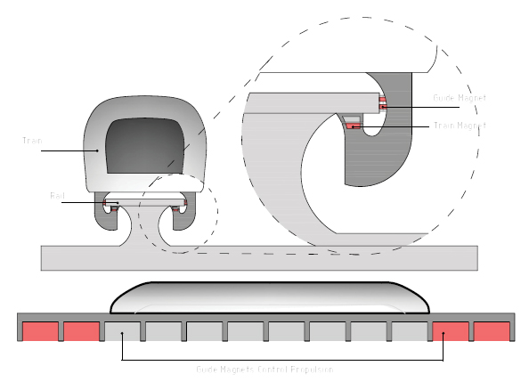
The beauty of maglevs is that they travel on air. The consequent elimination of friction means
much greater ef! ciency. Just as electrons move more ef! ciently through a superconducting wire
because there is no resistance, so maglev travels more ef! ciently than a regular train because
there is no friction between the wheels and the track.
The train itself is equipped with several superconductors, while a series of electromagnetic coils
run along the length of the track. When the train approaches these coils, the superconductors induce
a current in them that works to both levitate the train several centimetres above the track and
to centre it between the guide rails.
That’s a pretty neat trick, but it gets much neater once you get the train moving.
That’s achieved by a second series of electromagnetic coils, which run alongside the levitation/
guidance coils. After the train reaches a certain speed, these propulsion coils kick into gear. They
receive a constantly alternating electric current that changes the polarity of the coils in such a
way that they are always arranged to push or to pull the onboard superconducting magnets of the
passing train. In essence it’s a motor. It is not a circular one, like the one in the automobiles, but
linear, running the length of the entire track.
Another Advantage of this system is that only the coils that are in the vicinity of the moving train
at any point in time need be engaged. Which means that there can be saved energy because not
all the track will be under electrical power.
These trains have also wheels, which after reaching 140 km/h will take of, like in the aeroplane
example. These wheels are also used for emergency situations and also as a secondary breaking
system.
In conclusion, these trains can be the future of the public system in the cities in between cities
and why not all around the globe.
this blog is dedicated to the Bucky Lab from the TU Delft faculty of Architecture. Within the mastercourse we design, develop and at the end build architecture and building construction related prototypes. Its a "get your hands dirty" approach in which the students learn how to translate concepts from sketch into working prototypes. We try to live the spirit of buckminster fuller: what ever you can imagine, you can also build!
Showing posts with label HOW IT WORKS. Show all posts
Monday, August 6, 2012
Thursday, July 26, 2012
HOW IT WORKS: FLETCHER CAPSTAN TABLE
by Ahmed Abbas Momin
The Fletcher Capstan Table is named after designer Fletcher David, its a kind of table which automatically expands from a small size to a larger one.
It is a round table capable of doubling its seating capacity and, in process of expanding it remains truly circular. The original idea for a table of this type was designed in the nineteenth century by a man named Robert Jupe, 1835. It was called as Jupe’s table Youtube Video initially round, and had an ingenious geometry and a similarly ingenious method of making it expand radially, changing from a small size to a table of larger diameter. However, Jupe’s tables could not store their own expansion leaves, were not truly round in every stage, and were slow and laborious to operate. The Fletcher geometry is similar in concept, but different in terms of expansion leaves. It’s minor changes, according to the species of timber used, as the table expands from small to large, and shrinks vice versa.
The top surfaces is made up of six pie shaped planks (figure 1), and an outer skirt in the manner of a drum table . Below this first layer (figure 5) there consist two more layers of planks , the second is made up of six arrow shaped planks (figure 5) and, under that, a large star shaped leaf. Below all of this lies the rotating mechanism and pushing mechanism, constructed with the combination of hard anodised aluminium and stainless steel. Table planks are made from aluminium honeycomb cored composite for absolute integrity and rigidity. The whole assembly is supported on a base of varying design.
The table can operate manually by rotation of the entire top, or electrically from a pocket sized remote control transmitting unit. All tables, be they manual or electronic, rotate through 120 degrees as they operate, and electronic tables can easily be converted to manual.
The table transforms from a small circular wooden table into a larger diameter by rotating its side while the extra wooden pieces (2nd layer planks) underneath the furniture in its small state and then automatically raises them up and adds them to the whole circular form of the table as you rotate and transform the furniture into a larger piece.
Each section is connected to an underlying frame structure, such that when the table top is rotated, the sections move radially outward, increasing the effective size of the table top . Once the table top has been rotated the left over space is filled by 2nd layer of planks which are pushed up during the process of rotating.
A method for manufacturing
Starting with table support structure and defining a central axis; mounting a table top over the table support structure such that the table top is rotatable around the central axis between a first angular position and a second angular position relative to the table support structure, wherein the table top comprises a guide plate having a plurality of guide slots and a plurality of separate table top sections disposed over a top surface of said guide plate, each table top section being movable radially along a respective one of the plurality of guide slots between a first radial position and a second radial position when the table top is rotated between the first and second angular positions relative to the table supporting structure; and providing a plurality of support elements between the guide plate and the table support structure, the support elements being arranged to support the guide plate relative to the table support structure, wherein the support elements are mounted on a portion of the table support structure, whereby the table top is arranged to rotate relative to the support elements
Another video of the table
The Fletcher Capstan Table is named after designer Fletcher David, its a kind of table which automatically expands from a small size to a larger one.
It is a round table capable of doubling its seating capacity and, in process of expanding it remains truly circular. The original idea for a table of this type was designed in the nineteenth century by a man named Robert Jupe, 1835. It was called as Jupe’s table Youtube Video initially round, and had an ingenious geometry and a similarly ingenious method of making it expand radially, changing from a small size to a table of larger diameter. However, Jupe’s tables could not store their own expansion leaves, were not truly round in every stage, and were slow and laborious to operate. The Fletcher geometry is similar in concept, but different in terms of expansion leaves. It’s minor changes, according to the species of timber used, as the table expands from small to large, and shrinks vice versa.
The top surfaces is made up of six pie shaped planks (figure 1), and an outer skirt in the manner of a drum table . Below this first layer (figure 5) there consist two more layers of planks , the second is made up of six arrow shaped planks (figure 5) and, under that, a large star shaped leaf. Below all of this lies the rotating mechanism and pushing mechanism, constructed with the combination of hard anodised aluminium and stainless steel. Table planks are made from aluminium honeycomb cored composite for absolute integrity and rigidity. The whole assembly is supported on a base of varying design.
The table can operate manually by rotation of the entire top, or electrically from a pocket sized remote control transmitting unit. All tables, be they manual or electronic, rotate through 120 degrees as they operate, and electronic tables can easily be converted to manual.
The table transforms from a small circular wooden table into a larger diameter by rotating its side while the extra wooden pieces (2nd layer planks) underneath the furniture in its small state and then automatically raises them up and adds them to the whole circular form of the table as you rotate and transform the furniture into a larger piece.
Each section is connected to an underlying frame structure, such that when the table top is rotated, the sections move radially outward, increasing the effective size of the table top . Once the table top has been rotated the left over space is filled by 2nd layer of planks which are pushed up during the process of rotating.
A method for manufacturing
Starting with table support structure and defining a central axis; mounting a table top over the table support structure such that the table top is rotatable around the central axis between a first angular position and a second angular position relative to the table support structure, wherein the table top comprises a guide plate having a plurality of guide slots and a plurality of separate table top sections disposed over a top surface of said guide plate, each table top section being movable radially along a respective one of the plurality of guide slots between a first radial position and a second radial position when the table top is rotated between the first and second angular positions relative to the table supporting structure; and providing a plurality of support elements between the guide plate and the table support structure, the support elements being arranged to support the guide plate relative to the table support structure, wherein the support elements are mounted on a portion of the table support structure, whereby the table top is arranged to rotate relative to the support elements
Another video of the table
Labels:
HOW IT WORKS
Subscribe to:
Posts (Atom)


